- Detalhes
0x01 graphic
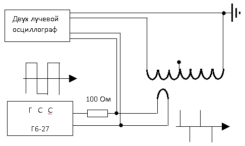
Fig. 33. The scheme of the installation for conducting experiments with a "zero - transformer" with a compensating part.
We will send a sinusoidal signal from the GSS to the inductor. Smoothly moving the inductor, we achieve curves close to zero on the oscilloscope screen from the output of the "zero - transformer". We have achieved curves close to zero - the setup is finished. We switch the GPS to the mode of generating rectangular pulses, for example, the frequency of 100 kHz. And, lo and behold! There were also pulses at the output of the "zero-transformer" - Fig. 34.
Fig. 33. The scheme of the installation for conducting experiments with a "zero - transformer" with a compensating part. We will send a sinusoidal signal from the GSS to the inductor. Smoothly moving the inductor, we achieve curves close to zero on the oscilloscope screen from the output of the "zero - transformer". We have achieved curves close to zero - the setup is finished. We switch the GPS to the mode of generating rectangular pulses, for example, the frequency of 100 kHz. And, lo and behold! There were also pulses at the output of the "zero-transformer" - Fig. 34.
- Escrito por: Newton C. Braga